Overview
This document describes how to use the collection of matlab functions and scripts, collectively called the Tokamak System toolbox or simply TokSys, which provides tools for tokamak system modeling and simulation, model validation, data analysis, and control design.
Help
If any description is incorrect or confusing, please contact Mike Walker at walker@fusion.gat.com.
This document focuses on the description of those portions of TokSys that are applicable to plasma shape and position control design, testing, and data analysis because the methods for those applications have been largely standardized. However, TokSys also contains a number of tools relevant for other control development and analysis tasks, both general (e.g. data access and signal processing) and specific (e.g., for control of NTMs, RWMs, ONFR, etc.).
All models produced using the tools described in this document use the convention that a positive toroidal current is a counter-clockwise current flow when viewed from above. Conductor voltages V are assumed connected such that V>0 causes coil currents Icoil to increase (in the absence of plasma). All data contained in the models described in this document use MKS units by default, i.e. Amps for current, Webers for flux, and Tesla for magnetic field. However, there is an option provided in some of the model calculation tools to produce data objects with currents in Mega-Amp-turns.
Any talks or publications containing results derived from the use of the TokSys toolset should contain an attribution for GA TokSys.
Linearized plasma models for boundary control development
The model building environment consists of matlab functions and scripts to perform the following major functions: - Construct tokamak data objects such as conductor resistances, mutual inductances, and other Green functions, which are all defined by the device geometry in the absence of plasma. - Read in a plasma equilibrium around which a linearized model will be generated. - Combine the tokamak information in (a) with the specified plasma in (b) to generate the linearized model (See equation 1). - Compare the derived linearized model with experimentally measured data, as part of a model validation process.
The TokSys toolbox has been used to derive models for the ITER, EAST, KSTAR, NSTX, MAST-U, DIII-D, SST-1, and Pegasus tokamaks, and the proposed Fusion Development Facility (FDF), among others. The developed models have been validated on DIII-D and NSTX and have been used to develop plasma controllers on DIII-D, ITER, EAST, KSTAR and Pegasus. Although even unvalidated or partially-validated models have proven very useful for developing and testing control software, use in a model-based control design requires that a real model-validation effort must be undertaken and completed before such controllers can be used with confidence in controlling plasmas. Model validation must include testing of individual component models, not just the final integrated model. Large integrated models are virtually never correct the first time used (or the 2nd, 3rd, ...) and typically cannot be made correct without identifying the source(s) of model discrepancy. Identifying sources of model discrepancy requires investigating individual components of the model.
The development and use of a common toolset for multiple devices has significant advantages beyond the obvious issue of software re-use. In all cases, the models generated are first principles physics models, constructed without any "tuning" or "fudge factors", except for use of direct measurements of certain quantities such as coil resistance or inductance. Validation of this type of model versus experimental data on existing devices provides confidence in both the modeling approach and the model implementation when using the tools to extrapolate to model generation for devices that do not yet exist.
Section 3 describes the modeling approach used by TokSys. Section 4 provides an overview of the organization and structure of the many modeling, analysis, and design functions. Section 5 provides instructions for how to make the Toksys tools available in your Matlab session. Section 6 provides a high-level summary list of device-independent modeling and analysis functions that are available when the Toksys tools are available in your session. Section 7 describes the process of constructing plasma response models, outlined in steps (a) through (c) above. Section 8 describes how the core set of generic modeling tools are used and expanded upon for modeling specific tokamaks and plasmas. Section 9 describes the process used for validation of TokSys models and the TokSys tools available to support this process. Section 10 describes a methodology employed to connect simulations constructed using TokSys models with a version of the real-time plasma control system (PCS), for those devices whose PCS is derived from the DIII-D PCS. Section 11 provides further details for some of the modeling tools. This section will be expanded in future versions of this document.
Plasma Control Modeling Approach
The set of modeling tools in this toolbox automate the majority of the process of generating dynamic models for the tokamak and plasma poloidal field systems involved in plasma shape, position, and plasma current control. Key products of the model development process are linear models of the form
that represent the dynamics of evolution of currents in toroidal conductors (control coils, passive structure, and plasma) within the tokamak and include the effect of the nonstationary plasma on these dynamics. Here, \(I\) represents the toroidal currents in coils, passive conductors, and the bulk plasma, \(v\) represents coil power supply voltages, \(y\) represents magnetic measurements such as flux, field, or current, and \(w\) represents disturbance inputs which can be used to model the effect of changes in \(\beta_p\), \(l_i\) , or of noise. The matrices \(\mathbf{A} = -(\mathbf{M}^*)^{-1}\mathbf{R}\) and \(\mathbf{B} = (\mathbf{M}^*)^{-1}\mathbf{V}\) are computed from the conductor resistance matrix \(\mathbf{R}\), a plasma-modified mutual inductance matrix \(\mathbf{M}^*\) (see [2]), and a matrix \(\mathbf{V}\) that maps power supply source voltages into voltages applied to control coils. The matrix \(\mathbf{C}\) is given primarily by the Green functions from currents to magnetic diagnostics, and \(\mathbf{D}\) is usually 0.
We refer to the first equation in \(\eqref{eq:dynamics}\) as the "dynamics equation" because it describes how the dynamical system defined by the collection of toroidal conductor and plasma currents evolves. We refer to the second equation in \(\eqref{eq:dynamics}\) as the "output equation" because it defines how the multiple magnetic diagnostics (B-probes, flux loops, coil and vessel Rogowskis, etc) depend on the toroidal currents and input voltages. The most basic and most mature plasma model construction method we use is based on the rigid plasma model approach described in [2]. Alternatives to this approach, including a nonrigid linear model [3] or nonlinear models [4] have also been integrated in this environment. Use of the nonrigid model requires only small variations from use of the rigid model, so we will confine the discussion in this document primarily to rigid plasma model development.
Note
Use of the nonlinear models will not be described here.
TokSys Toolbox File Structure
The TokSys toolbox consists of a large collection of matlab functions organized into separate Linux directories according to similar functionality. There are three types of matlab files used for modeling:
- TokSys Matlab functions and models, generically applicable to any tokamak.
- Device-specific matlab functions and models, which invoke the TokSys modeling tools.
- General Matlab functions, which are invoked by both of the above.
A TokSys installation consists of all three of these function sets plus additional tools for other related modeling and analysis purposes. The directory structure for such an installation is illustrated below.
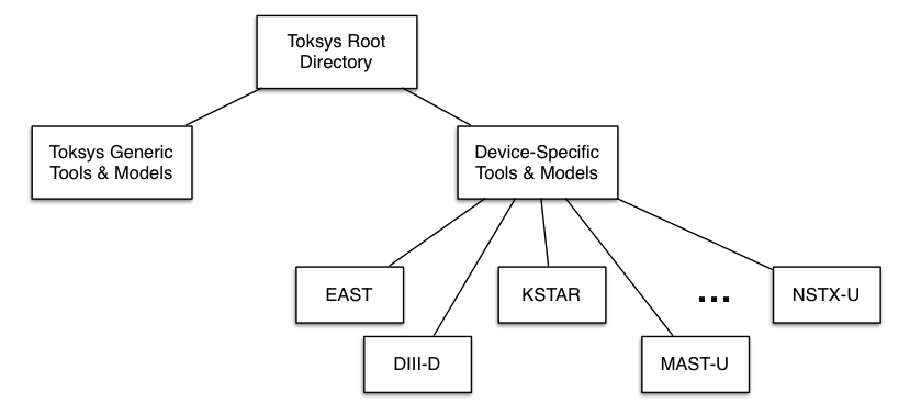
The TokSys general modeling functions and generic matlab functions are located under the matlab path in the above figure.
Device-specific functions are located under the tokamaks path.
In addition to these two sets of directories, the TokSys toolset sits "on top" of the ITER PCSSP (Plasma Control System Simulation Platform) toolset, whose directories are structured similarly (see below).
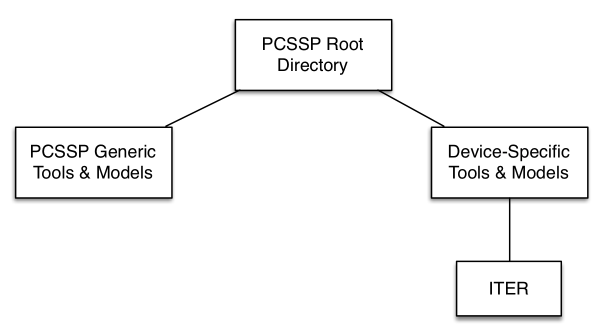
Codes and models specific to ITER are maintained as part of PCSSP, using the same separation between generally-applicable and device-specific functions and models.
The structure shown in the figures above represent the installation at DIII-D. Most installations will have only one of the device directories under the "tokamaks" branch of Toksys, i.e. corresponding to the device local to where the toolset is installed.
TokSys follows the usual matlab convention for providing on-line documentation to users in the form of function header documentation and Contents.m files. Each subdirectory in TokSys contains a Contents.m file that provides a summary of functions available in that directory. This summary of functions is available at the matlab command line by typing "help" followed by the directory name. Each function or script contains a standard format header, which describes how to use the function. This description is available at the matlab command line by typing "help" followed by the function name.
Note
These tools can serve as the foundation for the construction of your own specialized set of functions for tokamak modeling. Source code for all functions is provided and therefore can be modified locally.
Warning
DO NOT modify the source files in the installed area. Instead, make a copy of the source file in a separate directory, modify it there, then add that directory name to the matlab path in front of the TokSys directories. Matlab executes the first version of a file that it finds in its search path.
TokSys Generic Function Directories
We provide here a list of the subdirectories of the matlab directory shown in Figure 1. These subdirectories are intended to contain matlab scripts and functions that are applicable to any of the tokamak models we support and, in many cases, generally applicable to any tokamak. While this objective has been essentially reached for most sub-directories, there are a few of the functional areas listed below that are still evolving.
3d- Three-dimensional electromagnetic analysis calculations
breakdown- Generic plasma breakdown/rampup calculations
circuit_models- Conductor circuit modeling functions
comm_tbx- Public domain Communications Toolbox (not well-tested)
design- Control design tools
dcontrol- Public domain Digital Control toolbox (not well-tested)
dina- Functions related to DINA plasma simulation code (not maintained)
dmp- Matlab DMP tools
efit- Functions related to EFIT reconstruction code.
GAcomm- GA-developed communication functions (mostly Ultra-Wideband)
GAcontrol- GA-developed control design utility functions.
GAgraphics- GA-developed graphics functions
GAsignal- GA-developed signal processing functions
geom- Tokamak geometry manipulation tools
jfit- Functions related to JFIT Magnetics Fitting Code
mag- Magnetics Calculation Tools
math- Math calculations
mdsplus- MDSplus data extraction and manipulation functions
ntm- NTM control functions
PCS- Generic functions for interaction with PCS. Applicable to any installation of the DIII-D PCS.
plasma_models- Functions for generating plasma (or plasma+device) models.
plresp- (NOT Generic yet)
pubgraphics- Public domain graphics functions.
RWM- Functions for developing or analyzing RWM control (not currently available)
regression- Functions for regression
simserver- Functions for creating simserver simulations (to connect with PCS).
teq- Functions for interacting with Corsica and TEQ. (NOT Generic yet)
tok_models- Functions for generating plasma (or plasma+device) models
toksim- Toksim library and support functions
utilities- Utility functions
validation- Functions for model validation